Eachinevr006
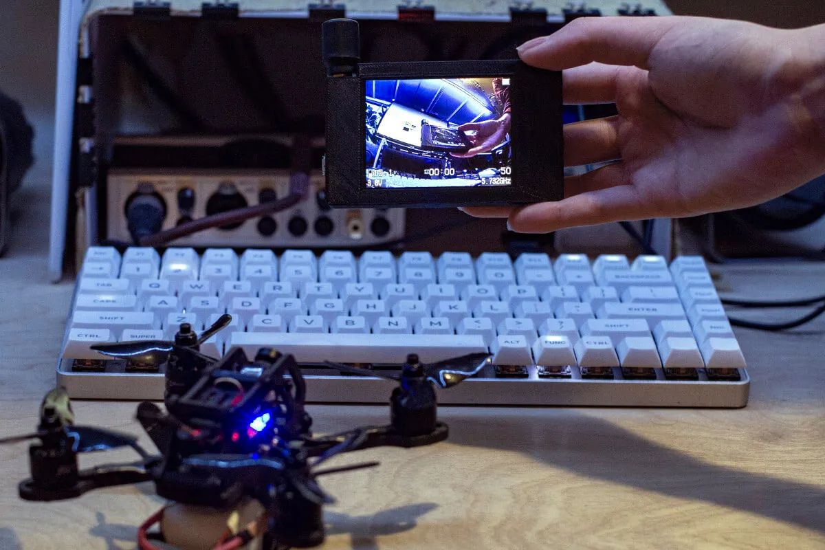
This project offers 3D printing files and instructions to re-house the screen and electrical components extracted from a cheap FPV headset Eachine VR006 to use as a stand-alone spectator screen for Drone Racing and other RF hobby applications.
A video version of this guide is available on youtube. 3D CAD models licensed under CC BY-NC-SA 4.0
Guide
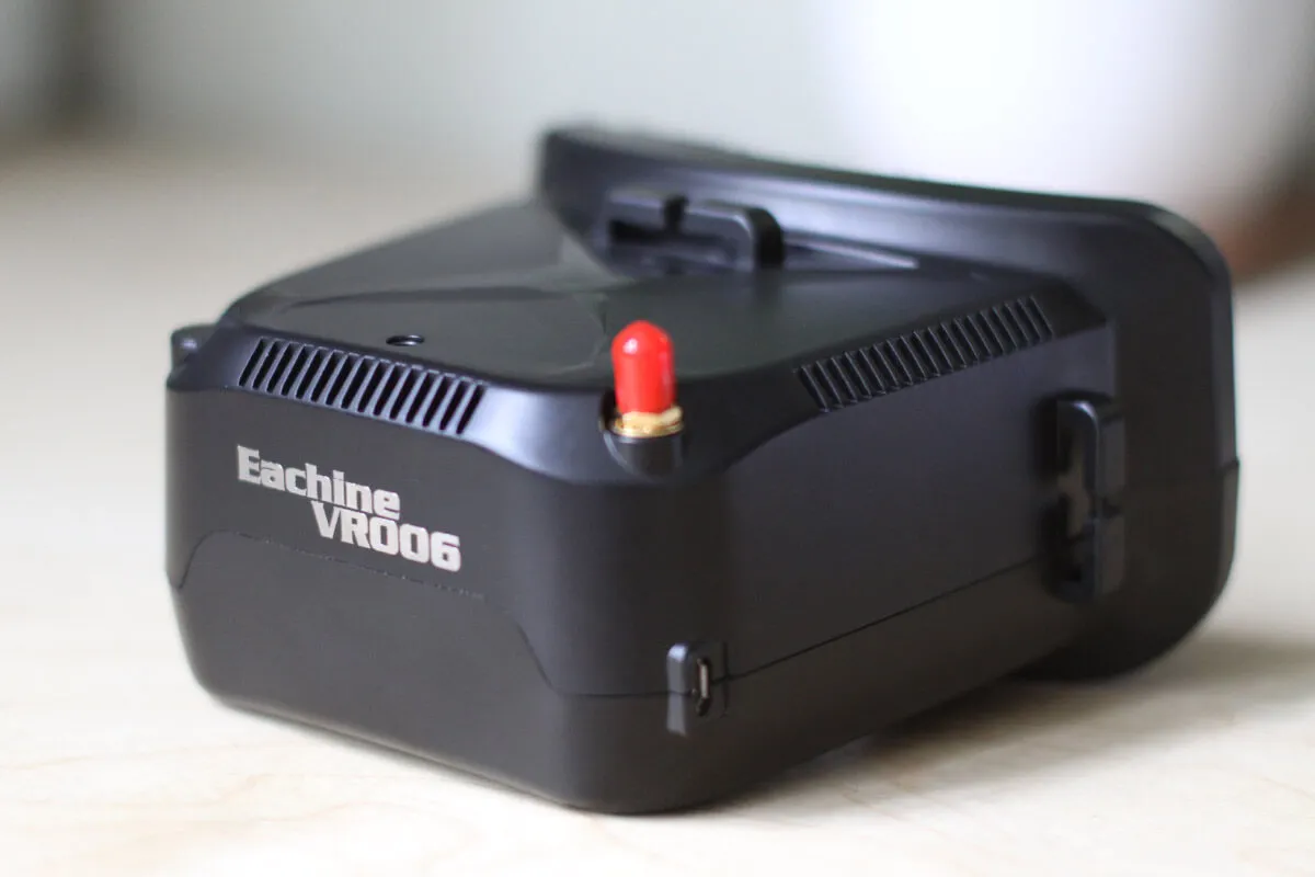
Step 1
Remove the SMA cover and the retaining brass nut.
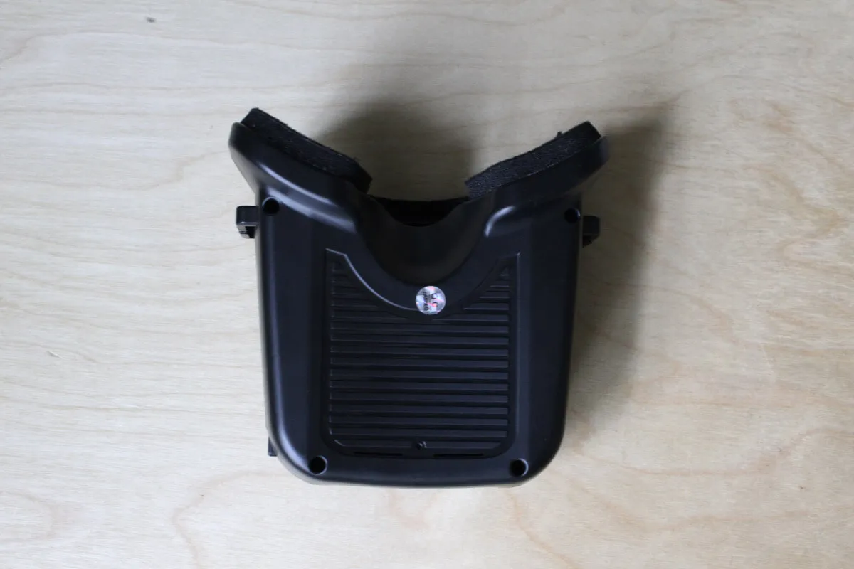
Step 2
Underneath, unscrew 4 phillips screws and lift the top half of the plastic body.
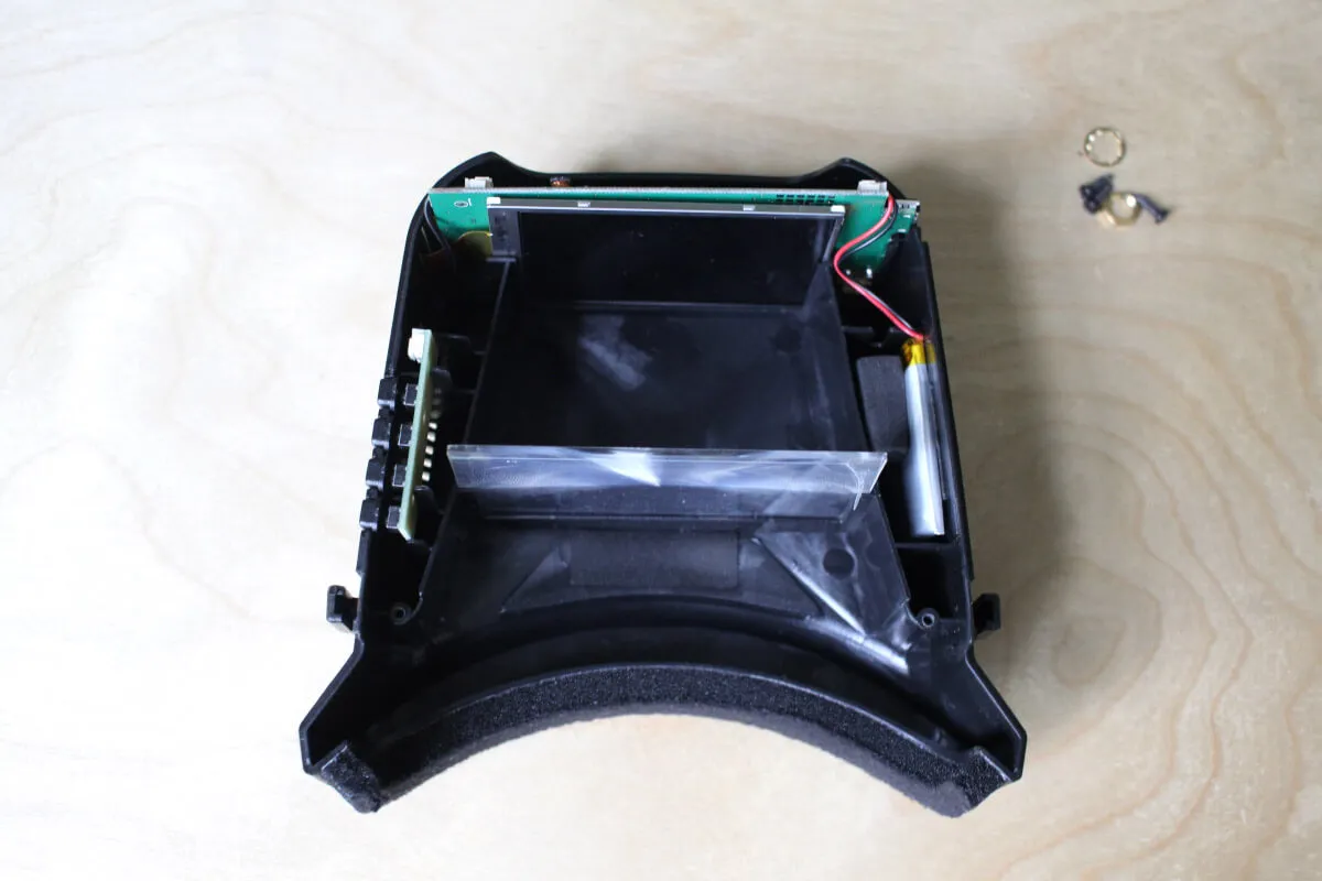
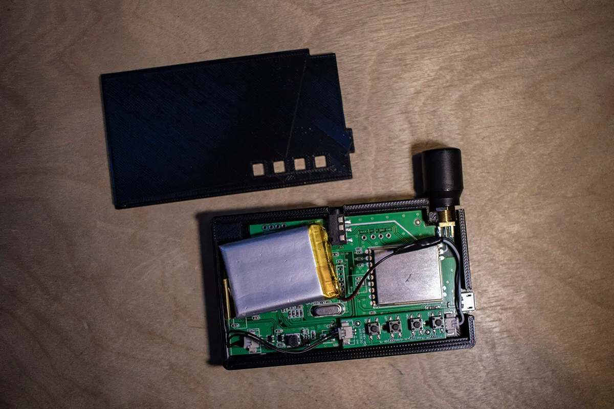
Step 3
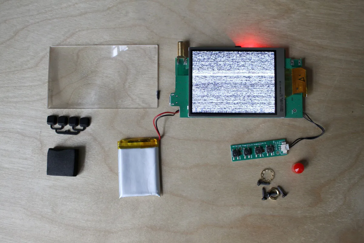
The battery is held in place with a piece of foam and double sticky tape. Remove the foam and carefully cut along the tape with a craft knife to avoid prying the lipo battery. Remove the control board and the fresnel lens. The screen assembly should freely slide out of the housing.
Step 4
Be careful removing the screen, as it's not attached to the circuit board. Pull them gently together to avoid damaging the ribbon cable.
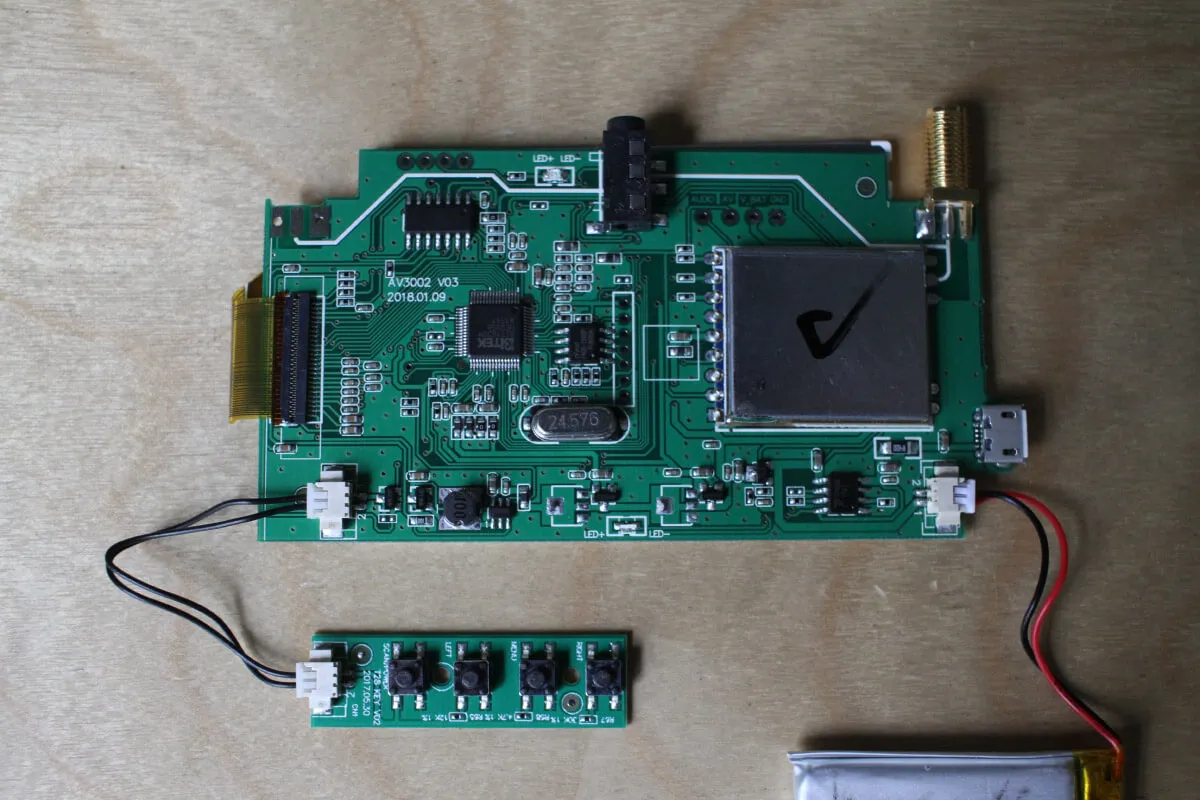
There are two variants of this board - the "diversity" version with two antennas (not real RX diversity) and the single antenna version I have here, my case design is for this version.
Step 5
Next, you'll tape up the exposed breakout pins to avoid short circuiting them when you secure the screen to the surface (the back of the LCD is metal).
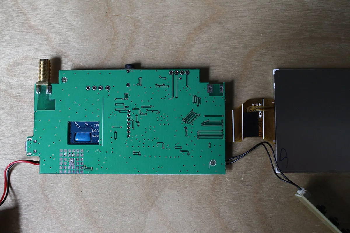
Cut some pieces of electrical tape to cover the breakout pins and gently press the screen onto the board to secure it with double sticky tape. Use double sided tape, foam tape will make the assembly too thick.

Step 6
Navigate to /STL/, download and 3D print the housing.
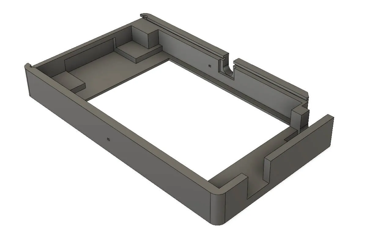
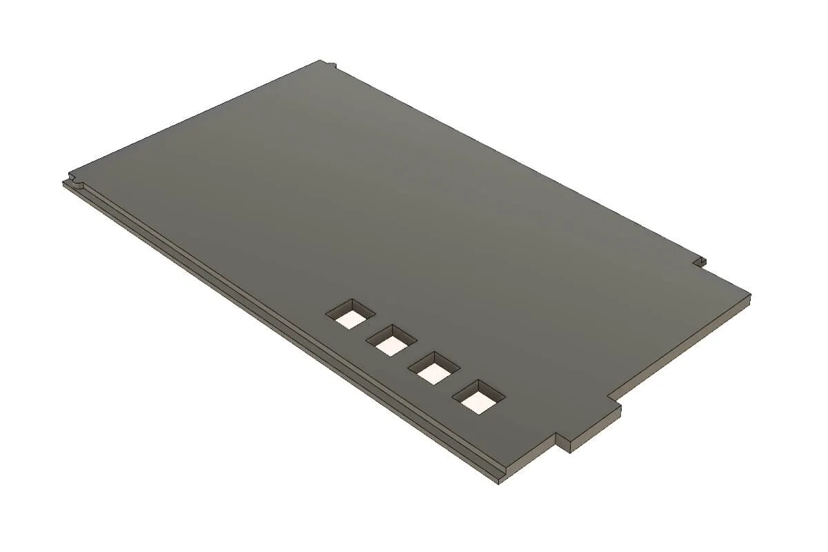
I created this to fit on a 10x10 printing platform, which is common among lowest-end printers. Due to this, the USB charging port sticks out a bit. If you want to make it flush with the side of the case, simply extrude the right wall by 3mm to the left.
Step 7
Remove the metal frame from the LCD panel. It will only get caught in the ridges of the 3D print and may actually damage your screen.
Step 8
Slot the assembly into the body of the case, ribbon cable side first, carefully allowing the case to bend it over the edge.
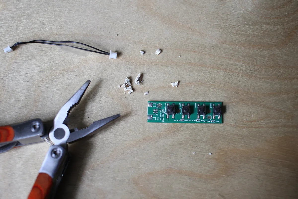
Step 9
De-solder the connector from the control board and re-attach the cables in order for the buttons to fit into the rear panel holes. Make sure to note which cable goes where, they're both black.
Step 10
Add some foam padding to the motherboard to sit against the control board to prevent it from sinking into the case when pressing the buttons.
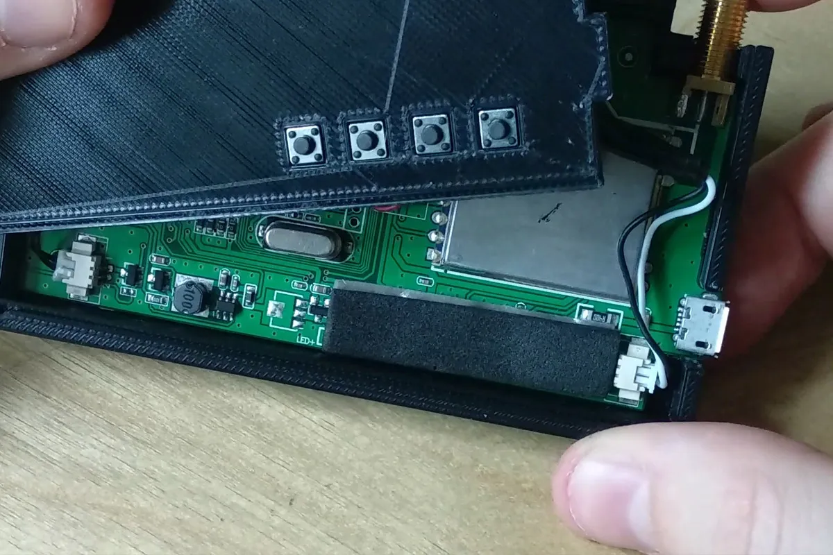
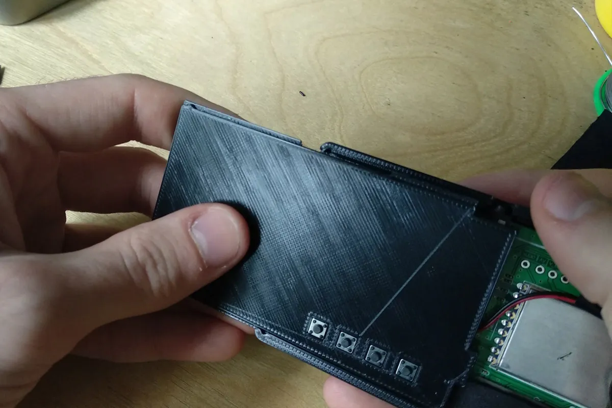
Step 11
Slot the rear cover into the bottom rail, aligning the top rail gaps then push it in to mesh both rails and slide the cover on.
Done!
Your screen assembly is now complete! Happy flying!